Before I finished Arcebus, people were
always asking me how it was coming along and what kind of boat it was, Both as a scrapbook
and a way to keep people informed, I documented the construction process on this page.
Now that she's been launched, I'm keeping it out here in case people are curious or
want to learn from my experience. One of the nice things about the web is it's
strictly voluntary -- if you don't feel like looking at this, you can just leave whenever
you want without offending me. If you are interested in seeing pictures of her in
action, you can go to my sailing log page, which is the home page for this site: Arcebus
Sailing Log.
What is an Arcebus?
I came across the word in a novel about resistance to the Spanish conquest of
Mexico. It was the name of an early matchlock gun. I picked the name because I
liked the way it sounded and because when you look at this boat you see a little bit of an
ark and a little bit of a bus.
Whatever compelled me to do this? Boat
building/sailing has been my primary hobby for many years. I have 4 homemade boats
(not counting Arcebus). So, why did I build another one? I admit it -- I'm
addicted. I like the challenge and the satisfaction that comes from building and
using your own boat. For me, there is no other activity that is as rife with
possibility. For every moment you spend working on the boat, there are ten that you
spend daydreaming about the ways you're going to use it, the methods you'll use building
it, the places you're going to go with it, and the adventures that you will be able to
share with others on it. Aside from a couple of simple kayaks, it's been 13 years
since my last boat-building project, 9 of which have been dominated with the intense
financial pressure of putting my three kids through college. For me, this was a
self-indulgence that I've been dreaming about, but unable to do for many years.
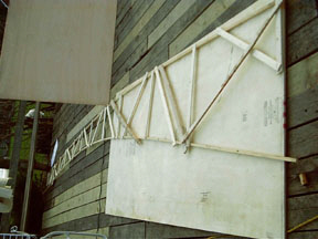
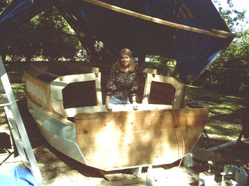
The boat is a hybrid of two
designs that I admire. The first is Jim Michalak's Jewelbox. I borrowed his
concepts of a 12 foot long, walk-through cabin, self-righting hull, transom bow from which
you can step onto the shore, and a pivoting leeboard. You can stay out of the sun
and stay warm on cold or wet days. For me, one of the biggest selling points is the
containment it provides for children. I have 2- and 4-year old grandchildren and I
see this as a great boat for camp-cruising with them. You can see these features in
the picture and appreciate their practicality, but you can also see that the hull is far
from a thing of beauty. The flat bottom would also pound like crazy when motoring in
a chop.
Michalak's Jewelbox 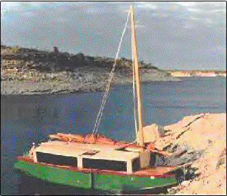
I just couldn't see
investing the amount of time it would take to build a boat that ended up looking like
that, so I played around with several alternatives. The first try was just a
whimsical effort at disguise -- could I make it look a little bit like a Balinese fish
boat (or at least a Minnesota musky)? It would be fun to take the grandkids sailing
in a big fish. With the help of my sister and brother-in-law, who is an Indonesian
artist, we came up with the following alternative.
Jewelbox in disguise 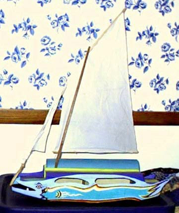 real Bali boats real Bali boats 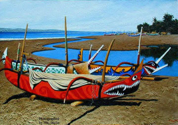
I finally decided the novelty might wear off and
I'd still be stuck with a boat that pounded badly in the waves.
I kept thinking about
ways to "improve" the hull form and finally focused on a hull that I was very
familiar with and enjoyed looking at -- the Nutshell Pram. The Nutshell Pram was
designed by Joel White and has been heavily promoted by Wooden Boat Magazine as a yacht
tender and small recreational sailor. When I say small, I mean small -- it's only
7'7" long. Still, it has very nice lines, is easy to build and, if stretched
out, is not too dissimilar in shape to the Jewelbox. Also, I was familiar with the
design and the glued lapstrake construction technique, having built several scale models
of the Nutshell Pram as childrens' rocking boats and as baskets and display models.
Why not put Michalak's cabin on Joel White's hull?
 view from the front
I increased the Nutshell's
dimensions pertaining to length by a factor of 2.4 and those pertaining to width by
1.8. This gave me an 18' hull that was just under 8' at its widest point.
Next, I made a 1/8 scale model, from which I have taken all my dimensions for the real
boat. Here it is:
Arcebus: the model. 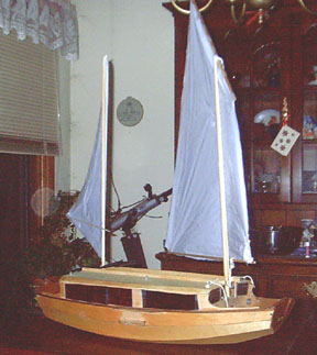
It's kind of hard to see in this picture, but I'll have a landing craft-type fold-down
ramp in the bow to help get in and out of the boat when beached.
Construction
Sails
I finished the model in January 2003 and started right away on the mainsail -- a good
mid-winter project. I used Michalak's sail plan, which calls for a balanced lug sail
of about 160 square feet. He provides all the guidelines needed for broadseaming and
shaping the sail. The biggest challenge was to lay it out and sew it within the
confines of my smaller-than-sail-sized living room. I had to keep rolling it up one
way or the other as I worked on it. I found it was a lot easier to get 22' of
rolled-up sail material through the sewing maching by ramping it down the stairs, through
the sewing machine, and onto the piano and a lineup of chairs. This gave me enough
floor-area to get the whole length through in one pass and also gave me a little bit of an
assist from gravity. My long-suffering wife, Pam, was very anxious for me to
complete this stage of the project.
I'm hiding in the shadows of the stairway in this picture 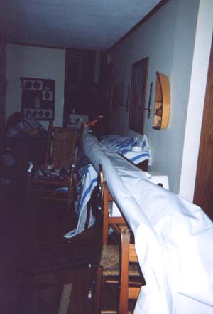
As shown on the model, I'm planning to experiment with adding a
mizzen sail in the back. Ths will give me a little extra sail area for light breezes
and should help provide better balance. The center of lateral resistance (pivot
point) is going to be further back than it is on Jewelbox because of the different hull
shape. The mizzen will also make it a lot easier to handle the large main because it
will help me face upwind when raising or lowering sail. I already have a 60 square
foot sail and mast left over from an earlier boat building project (Phil Bolger's Gypsy)
which should serve nicely as a mizzen. I think I've worked out pretty well the
location of the combined center of effort of the sails and the pivot point of the
hull. I may be in for some surprises, though, so I'm planning to leave a lot of room
for adjustment in mast angle (rake) and leeboard location. The biggest concern I
have is whether the boat will be able to stand up to that much sail. My attitude is
I'd rather have too much than too little. I can always reef down and even if the
boat gets knocked completely down it will not fill with water. (If all goes as
hoped, it will also be self-righting.)
I've decided, too, that I'm going to use two pivoting leeboards
instead of a single one as Michalak uses. Arcebus has a much narrower bottom than
Michalak's flat-bottomed boats and is going to heel over more when it's sailing. I'm
worried that a single leeboard won't have enough submerged area when it's on the weather
side and the boat is heeled. This could really be a problem if I need to get away
from a leeward shore. Also, having 50-60 pounds of weighted leeboard always hanging
out on the windward side is ideal ballast which should help it stand up to the wind and
contribute to self-righting capability.
Mast and spars
Michalak's plans call for a solid mast built of laminated 2 X 4s. I decided
to do it the easy way and use a tree. A few years ago, a stand of spruce at my
mother's lake place fell victim to the spruce beetle. I chopped down the nicest
looking ones and put them under the cabin to dry. I hauled one home this spring.
At 22' in length, it's straight and weighs 30 pounds. It's just under 4
1/2" at it's widest point and tapers to 2 1/2" at the top. I glassed the
top 3 feet for added strength. In a balanced lug rig, the peak of the sail is
supported by a top yard and extends much higher than the top of the mast. I made the
12' top yard from some Sitka spruce offcuts I still have from a catamaran mast I built 20
years ago. My 14' boom is from an old Douglas fir stair rail that I've been saving.
Lofting
Lofting is the process of drawing patterns for the molds around which the boat is built.
Having already built a model, I simply scaled everything I used for the model up by
a factor of 8 and drew patterns on a sheet of plywood. Thank God for the metric
system -- will we ever get smart enought to make the conversion?
Of course the problem with scaling up is that a measurement error of 1 millimeter on the
model translates into an error of 8 millimeters in the full-scale lofting. I was
prepared to have to do a lot of shimming and trimming when I set up my molds and fit my
planks, but was pleasantly surprised to find that no adjustments were necessary.
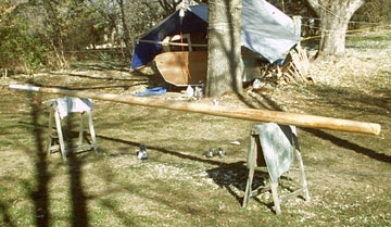
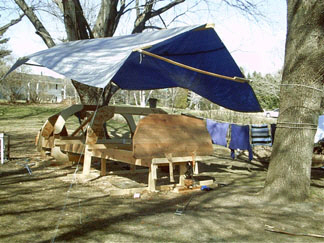
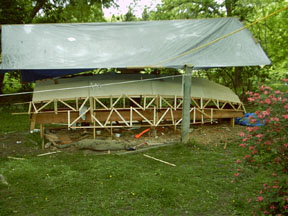
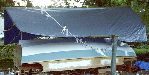
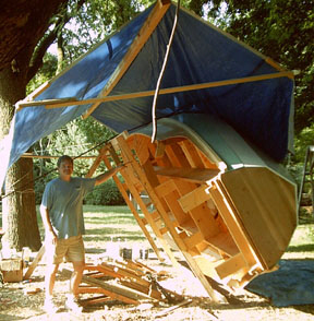
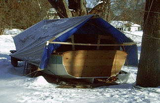
Flying Boat Shelter
Since I was building the boat in the back yard, I needed a shelter from the rain.
I came up with what is probably the simplest and cheapest possible type of
structure -- a tarp suspended between two trees. It has kind of a "no visible
means of support" look since the 1/8" cable that suspends it is hard to see.
The cable runs through a sandwich of two 20' 2 X 4s in the area of the tarp.
Unfortunately, during a spring snow storm with sustained 40+ mph winds, a turnbuckle hook
straightened out and it all came crashing down.
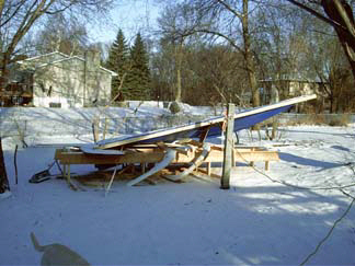
I replaced the turnbuckle with a rope and pulley system at each end
so that I can lower the shelter in high winds and subsequently weathered many storms and a
Minnesota winter with no further problems.
Building Jig and Frames
I set up the molds and transoms on a strong-back made from two 20' 2 X 10s.
Except for the dimensions, the set-up is exactly the same as for the Nutshell Pram.
(Complete plans for the Nutshell Pram were published in Wooden Boat in 1984, volume
60.) The bow and stern transoms were made from 2 X 6 cedar boards, which I
edge-glued with splined joints. The middle frame is a permanent one (made of 2 X 6
cedar with heavy 3/4" plywood gussets) but the other two are temporary.
Two permanent frames were added after the planking was glued on -- one to serve as the
front cabin wall and the other to serve as the rear cabin wall.
Planking
The planking is plywood -- 2 layers of 1/2" on the bottom, 1 layer of
1/2" for the garboards (the first planks up from the bottom), and 1/4" for the
top two planks, the topmost of which also forms the cabin walls. The extra strength
and weight below will provide impact resistance and (I hope) self-righting ability.
I spent less than $400 for the plywood in this boat. It took 8 sheets of 1/2"
lauan plywood at $30 per sheet and 16 sheets of 5' X 4' X 1/4" "Baltic
Birch" at $8.88 per sheet. I bought all of it at Menards. All pieces
were 5-ply, void free, had excellent faces on both sides, and were glued with exterior
glue. The birch, which is sold as underlayment, will be beautiful in the inside of
the boat. Birch has little rot resistance, but every piece I use will be covered
with glass and epoxy, and will be above the waterline. It is tough stuff, with
beautiful faces that need very little sanding and no patching.
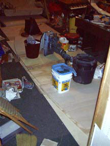
Those sheets of plywood had to become long planks. I used
Dynamite Payson's method of scarfing -- butt joints held together with fiberglass
tape. Lay out some wax paper, wet down a 2-3" wide strip of fiberglass on the
wax paper with epoxy, lay down the plywood so it butts in the middle of the strip, apply
epoxy and fiberglass to the top of the joint, cover with wax paper, and apply weight to
spread the epoxy out and get the the edges of the planks are in the same plane. Here
is a picture of the first bottom layer of the boat after applying tape and epoxy. I
have placed just about every heavy object I can get my hands on over the joints.
Because of the number and length of the joints here, I only did one side at a time.
 Carrying the finished panel
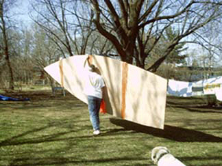
Spiling the Planks
Spiling is the process of creating planks that are the exact shape that are
needed. After attaching the full-sized bottom and laminating another 1/2-inch layer
on top of that, the edges of the bottom were trimmed to size and beveled to provide a
gluing surface for the next planks (the garboard planks). Below to the left is a
picture of my pattern for the garboard. The pattern is easily made with two battens
(long thin strips) and cross-hatched bracing. After fabricating one set of planks,
the pattern is dismantled and rebuilt to match the shape of the next plank. In
this type of construction, the edge of each plank is beveled to a knife edge and serves as
a gluing surface for the next plank. The picture on the right shows how the pattern
was constructed for the top-most plank. A small electric bad gun was very helpful
for attaching the cross-bracing. Wherever I lapped two 1/4-inch thick planks on this
boat, I backed up the joint with a 3/4" X 1 1/2" battens, which were let into
the molds and notched into the transoms. This increases the rigidity in the long
spans between frames and to provides added gluing surface for greater strength.
I glued the garboards on immediately after fabricating them, but the
top two planks were only temporarily fastened. After building and fitting them, I
removed them and glassed them on both sides before gluing them on permanently. It is
much easier and cleaner to sand and glass them when they are lying flat on saw horses than
when they are hanging on the hull.
Xynoling the Bottom
Instead of using fiberglass on the bottom and the garboards, I used a fabric
called Xynole (also known as Dynel). Xynole is made of a polyester and is much more
abrasion-resistant than fiberglass. I used two layers on the bottom and one layer on
the garboards. The bad thing I discovered about Xynole is that it sucks up epoxy
like a sponge. I felt like my budget was going to go through the roof. I'm
going to end up using about 11 gallons of epoxy for the whole project at $65/gallon --
definitely the most expensive item in the boat. I will have a strong bottom, though,
with a full inch of plywood and about 3/16" of Xynole/epoxy. Xynole sands
poorly, but I discovered that you can easily shave off any overlaps or high areas with a
sharp block plane and it doesn't dull the blade.
Here I am pouring more liquid gold into the black hole 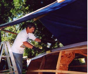
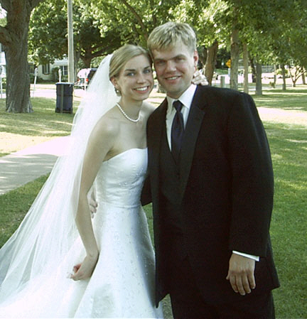
Timeout for a Wedding
Not much boatbuilding for awhile -- my beautiful daughter Krista is married in August
.
It was a wonderful wedding!
Building the
Permanent Frames
at the Cabin Ends
Before I could attach the top plank (which includes the cabin sides), I had to
build in the permanent frames which are located at each of the cabin ends. Doing
this in the upside-down boat was the most difficult and putsy part of the project. I made these
of cedar 2 X 4s sandwiched by sightly wider birch plywood, which served as gussets to hold the 2X4 pieces together. After turning over the boat,
I added cherry trim to cover the openings between the plywood edges.
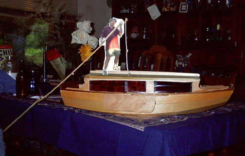
Power Plant
I have two back-up plans for when there is no wind. The first is a long
sculling oar called a yuloh. The yuloh has been used for thousands of years in the
far east. The long blade stays parallel to the surface of the water, but because it
is beveled on top, it supposedly develops lift like an airplane wing when sculled back and
forth. It may be simpler to say that the angle of the blade makes it want to dive
down when pushed sideways through the water, but it is restrained by the rope that runs
from the end of the oar to the boat hull. The downward thrust is, thus, transferred
into forward thrust which propels the boat. The thrust is continual as the oar
wiggles back and forth without the slowdown that you get between strokes in rowing.
The picture below is a shot of yours truly navigating across the dining room
table in the model Arcebus.
My second back-up plan is an old 5.5 horse Evenrude (recently updated to a 5 horse long shaft propane powered Tohatsu)
which hangs on a mounting box on the transom that is easily raised and lowered. It's enough to maintain
hull speed in just about any conditions.
That was my original concept -- the picture below flash-forwards 2 years to show the
curved yuloh that I actually installed which allows me to operate it within the cabin.
I found the little curved tree for the shaft while canoing in northern Minnesota.
The yuloh pivots on a trailer-hitch ball mounted on the transom. The socket is a sawed-off trailer hitch
receiver lag-screwed to the yuloh. A removeable pin is used to secure the receiver to the ball, while allowing it full range of motion.
Note: In 2013, I added a hinged 3' extension to the blade to give me more power while still fitting inside the boat.
Ready for Turning
As of September 4, the bottom is painted and the boat is ready to leave the
security of its building jig. Here's what it looks like:
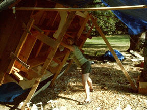
Turning it Over -- Saturday
morning, September 5
My long-suffering wife, Pam, does the heavy work. I do the precision work.
Actually, this was a pretty easy 1-man job with a couple of car jacks and a stout
rope wrapped around a tree to control the landing. Glad I had the foresight to
attach 8' 2X4s to the legs of the jig when I built it.
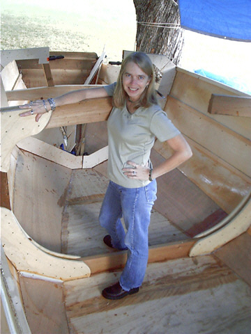
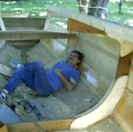
Examination by my long-suffering
wife, Pam
You said this had a cabin. So where's the bathroom? Where's
the kitchen? Where's the standing head room?
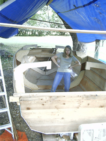
She brightens up after a few lies.
Yeah, and I'm almost
done, too
.
A figurehead might be a nice touch
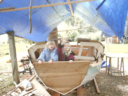
Bon Voyage!
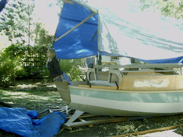 
Annika and Camilla (grandkids) are
ready to go sailing
By the end of September I'm realising that it's not going to make it into the water before
next spring. I thought for sure I'd be farther along, but what with the wedding and
other responsibilities, weekends and the odd Friday just weren't enough to get it done in
one summer. It's getting too cold for gluing and the days are getting shorter.
If I'm lucky, I'll get the roof and the decks on before the snow flies. If not, I'll
just cover it well and finish it off in the spring. Gee, that gives me the whole
winter to plan some cruises.
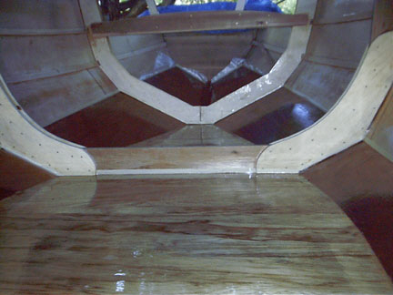
October 9 -- An unheard-of 3 consecutive October days of 80 degree
weather inspired me to put down 3 coats of epoxy on the floor. Now I don't have to
worry if I get a little rain water or snow melt in the inside. The dark mahogany
color of the garboards make for quite a contrast with the birch planks above. I selected
the lighter lauan below because of its interesting grain pattern.
Time
to hang it up until spring
of 2004
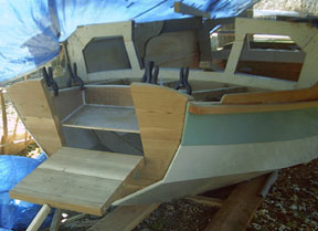
As of November 11th and I closed the book on Arcebus for the year to tackle the
long list of honey-dos that Pam has let me avoid for so long. I've got the decks
framed and have spiled and cut out the panels for the cabin roof. The picture below
shows how the fold-down ramp and step-up at the bow are going to look.
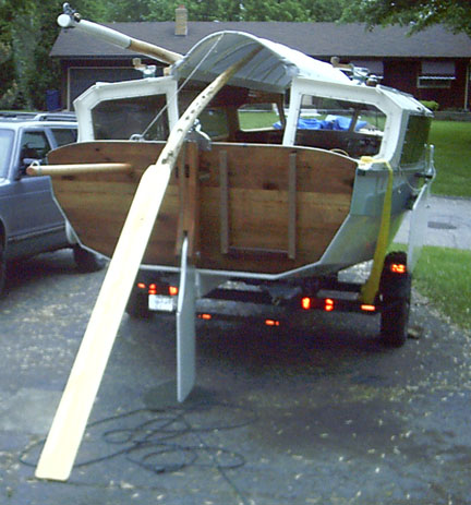
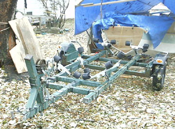
One more thing -- I found a trailer! Took a drive in rainy
mid-November to the the biggest new and used boat dealer around and found the perfect
trailer for Arcebus for $300 (it pays to shop in November). This is one solid
trailer, with just enough width between the fenders. Yippee!
That's all until springtime -- thanks for visiting.
Second Summer of Construction. No, I didn't finish it
then, either, but I came close.
|